sábado, 15 de abril de 2017

Crear un túnel vpn entre 2 mikrotik con ip dinámica

In this post we are going to create an IPsec VPN tunnel between two remote sites using Mikrotik routers with dynamic public IPs . By default, Mikrotik does not allow to use FQDN (domain names) to setup an IPsec tunnel, so we are going to create some scripts to update the IPsec configuration whenever the local or remote IPs change.
The network layout is as follows:


Mikrotik IPsec

The first thing to take into account is that LAN addresses must be different between Site 1 and Site 2. In our example, Site 1 uses LAN 192.168.1.0/24, whereas Site 2 uses 192.168.2.0/24. You can replace these networks with the ones in your infrastructure.
Another thing to consider is if your routers are behind a NAT. In this case you will have to make sure to forward port 500 (UDP) to the Mikrotik router.
In order to configure the IPsec tunnel, we have to setup the proposal, the peer, and the policy. We are going to provide the commands to configure Site 1, so once you finish with the guide, start over reverting the source and destination LAN addresses to configure Site 2.
First, let’s create an IPsec proposal:
/ip ipsec proposal add name=proposal1 auth-algorithms=md5 enc-algorithms=3des pfs-group=modp1024 disabled=no
Now, let’s create the peer. Replace the “test” secret with whatever password you want to use. Leave the address as it is as we will update it later from a script.
/ip ipsec peer add address=10.0.0.2 port=500 auth-method=pre-shared-key secret=test send-initial-contact=yes nat-traversal=no proposal-check=obey hash-algorithm=md5 enc-algorithm=3des dh-group=modp1024 generate-policy=no comment="myIPsec"
And, finally, let’s create a policy that will identify interesting traffic that should go through the IPsec tunnel. Again, let’s leave the “sa-src-address” and “sa-dst-address” as shown.
/ip ipsec policy add action=encrypt disabled=no src-address=192.168.1.0/24 dst-address=192.168.2.0/24 level=require ipsec-protocols=esp protocol=all tunnel=yes sa-src-address=10.0.0.1 sa-dst-address=10.0.0.2 proposal=proposal1 comment="myIPsec"
The IPsec portion is now configured in Site 1. But we need to add a couple of NAT rules to accept the IPsec traffic.
The following NAT rule will allow us to reach IPs on the remote LAN from our local network. It is important that this rule is placed in the first position.
/ip firewall nat add chain=srcnat src-address=192.168.1.0/24 dst-address=192.168.2.0/24 place-before=0 action=accept comment="IPsec traffic NAT bypass"
Add also this rule If we do not already have a NAT rule to masquerade internal traffic.
/ip firewall nat add chain=srcnat src-address=192.168.1.0/24 place-before=1 action=masquerade comment="Masquerade internal network"
Now, we need to create an account in a dynamic DNS service that will allow the remote site to always find out the other site’s public IP. In this guide we are using the No-IP.com service and provide scripts to update the IP of No-IP hosts. You are free to use whatever dynamic DNS service you want.
Once you have created an account and a host for Site 1, go ahead and the following script to update the No-IP host and the IPsec policy in the event of an IP change.
The script source is located here: https://gist.github.com/adrianmo/e54fbcd2c9d3cce80260
It may be more convenient to create the script from the UI, whether it is the web UI or Winbox. Enable “read”, “write”, and “test” policies, paste the script in the source field and replace the variables within the “Script Settings” section with your information. If you have followed the guide, leave the “IPsecComment” variable as it is. Replace the “WANInter” with the WAN interface that has the public IP of Site 1.


Mikrotik IPsec

You can run the script manually and check the logs to verify whether the No-IP host and the IPsec policy are updated successfully.
/log print
Now we need to create an scheduler to run the script every time period. We considered that a 10 minute interval is quite balanced, but you can adjust it to your particular needs.
/system scheduler add disabled=no interval=10m name=no-ip_ddns_scheduler on-event=”no-ip_ddns_update” policy=read,write,test start-date=jan/01/1970 start-time=00:00:01
At this point Site 1 No-IP host should update automatically whenever its public IP changes and will also update the IPsec policy accordingly. Now we need to update Site 2 public IP in the IPsec peer and policy configuration, so create a No-IP host for Site 2 if you don’t have it already. Do not worry about the IP that this host is resolving to, it will be updated in Site 2 when we repeat the steps on Site 2.
The script to update the IPsec peer and policy when Site 2 public IP changes can be found here: https://gist.github.com/adrianmo/92e305123b521b7a4400
Again, create a script from the UI and replace “RemoteNOIPHost” with the host name of Site 2.


Mikrotik IPsec

You can run the script manually and check the logs to verify that the IPsec peer and policy are updated successfully. For testing purposes, you can manually modify the IP from the No-IP control panel and verify that the script updates the IPsec configuration with the new IP.
/log print
We are now done with the configuration on Site 1, so it is time to move to Site 2 and go through it again configuring the IPs in the reverse order.
If you feel so inclined, please let us know how it went and leave some feedback if you find it useful.


Fuente:
http://www.devcows.com/blog/create-an-ipsec-tunnel-between-2-mikrotik-routers-and-dynamic-public-ips/

IPsec tunnels

Preface

IPSEC is one of the most commonly used VPN technologies to connect two sites together over some kind of WAN connection like Ethernet-Over-Fiber or Broadband. It creates an encrypted tunnel between the two peers and moves data over the tunnel that matches IPSEC policies.

Navigation

  1. Nomenclature
  2. IPSEC Policy vs Routing
  3. IPSEC Topology
  4. Mikrotik IPSEC Peers
    1. Seattle Peer
    2. Boise Peer
  5. Mikrotik IPSEC Policy
    1. Seattle Policy
    2. Boise Policy
  6. Mikrotik NAT Bypass
    1. Seattle NAT Bypass
    2. Boise NAT Bypass
  7. IPSEC Tunnel Testing

Nomenclature

"Peers" and "Policy" will be used a lot in this article, so it's important to know what they mean. Peers are the endpoints for IPSEC tunnels. Policies are the settings that define the interesting traffic that will get pushed over the tunnel. If packet traffic isn't covered by a policy it isn't interesting, and gets routed like any other traffic would be. If packet traffic does match what's in a policy, the router defines those packets as interesting, and sends them over the tunnel, rather than routing them.

IPSEC Policy vs Routing

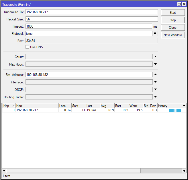
There's a very important distinction that needs to be made here - IPSEC isn't routing. IPSEC doesn't create virtual interfaces that are added to a route table like PPTP or GRE do. IPSEC isn't based on routing, it's based on policy. In fact in the diagram below when tracerouting from one LAN subnet to another through two branch routers and multiple Internet routers only one hop is seen.

IPSEC Topology

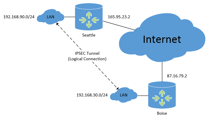
Below is the physical topology diagram of what we're working with, and it shows the logical connection that the IPSEC tunnel will create between subnets. Mikrotik IPSEC Topology
We have two routers, in Seattle and Boise, both connected to the Internet somehow with their own static IP addresses. These routers could be at two offices owned by one company, or just two locations that need to be connected together. We need computers or servers at one location to be able to contact devices at the other, and it has to be done securely. An IPSEC VPN is perfect for this sort of implementation.

Mikrotik IPSEC Peers

First, on each router we'll configure IPSEC peers. The peer will point to the opposite router's public IP address, with Seattle pointing to Boise and Boise pointing to Seattle. It's very important to add comments to your peer and policy entries, so you know which points to which.

Seattle Peer

On the Seattle router:
/ip ipsec peer add address=87.16.79.2/32 comment="Boise Peer" enc-algorithm=aes-128 nat-traversal=no secret=my_secret

Boise Peer

On the Boise router:
/ip ipsec peer add address=165.95.23.2/32 comment="Seattle Peer" enc-algorithm=aes-128 nat-traversal=no secret=my_great_secret
The encryption algorithm and secret must match, otherwise the IPSEC tunnel will never initiate properly. In production networks a much more robust secret key should be used. This is one time when network administrators often generate long random strings and use them for the secret, because it's not something a human will have to enter again by memory. Secret keys should be changed on a regular basis, perhaps every 6 or 12 months, or more often depending on your regulatory needs. Do not enable NAT traversal, it's pretty hit-or-miss. This feature is meant to help get around NAT'ing, which breaks IPSEC, but it doesn't always work necessarily.

Mikrotik IPSEC Policy

Second, we'll configure the IPSEC policies. These are what tells the router was traffic is "interesting" and should be sent over the tunnel instead of routed normally. Because this IPSEC tunnel will be a site-to-site tunnel connecting two networks (instead of hosts) we'll specify tunnel=yes in the configuration. This is also required per Infrastructure Router STIG Finding V-3008:
...ensure IPSec VPNs are established as tunnel type VPNs when transporting management traffic across an ip backbone network.
https://www.stigviewer.com/stig/network_devices/2015-09-22/finding/V-3008
If you look at the policies side-by-side you'll notice that the IP address entries on both routers are reversed - each router points to the other. It really helps to open up the same dialog boxes in two Winbox windows, looking at them side-by-side, checking that the SRC address on one router is the DST address on the other.

Seattle Policy

On the Seattle router:
/ip ipsec policy add comment="Boise Traffic" dst-address=192.168.30.0/24 sa-dst-address=87.16.79.2 sa-src-address=165.95.23.2 src-address=192.168.90.0/24 tunnel=yes

Boise Policy

On the Boise router:
/ip ipsec policy add comment="Seattle Traffic" dst-address=192.168.90.0/24 sa-dst-address=165.95.23.2 sa-src-address=87.16.79.2 src-address=192.168.30.0/24 tunnel=yes

Mikrotik NAT Bypass

If you're using NAT to send multiple internal LAN IPs out one interface to the Internet we'll need to bypass that. If we don't set up a NAT bypass the NAT process will snatch up our traffic before the IPSEC policies have a chance to move it over the tunnel, and those packets will get NAT'd out into oblivion. We'll create these NAT rules on each router, and move them up above any others.

Seattle NAT Bypass

On the Seattle router:
/ip firewall nat add chain=srcnat comment="Boise NAT bypass" dst-address=192.168.30.0/24 src-address=192.168.90.0/24

Boise NAT Bypass

On the Boise router:
/ip firewall nat add chain=srcnat comment="Seattle NAT bypass" dst-address=192.168.90.0/24 src-address=192.168.30.0/24

IPSEC Tunnel Testing

At this point we have everything needed for a functioning IPSEC tunnel. With that being said, most routers do not keep IPSEC tunnels up all the time. If no interesting traffic is being pushed over the tunnel most routers tear the tunnel down and don't bring it back up until the policies are triggered again with interesting traffic. This can create a tiny bit of latency when traffic first starts, a moment is needed to build the tunnel. RouterOS features like Netwatch and scheduled ping scripts can create traffic that keeps the tunnels up, but you shouldn't see an appreciable difference, especially if you're moving data frequently from one subnet to another.
For IPSEC tunnels that stay up all the time and also give you routed virtual interfaces, take a look at running GRE over IPSEC.
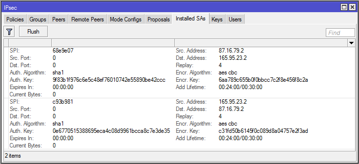
To force this IPSEC tunnel to come up I've sent pings from one subnet to the other, creating interesting traffic and triggering the IPSEC policy. When viewing the Installed SAs on the Boise router we can see that encryption keys have been established, and that on each side the SRC and DST addresses correspond with each other: Mikrotik Installed SA
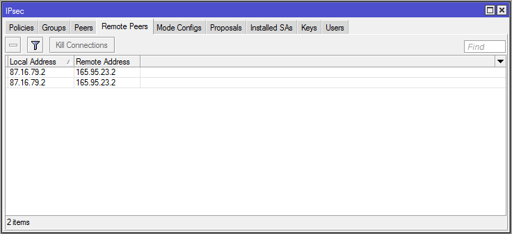
In the Remote Peers tab it also indicates that the Seattle router is an established remote peer: Mikrotik IPSEC Remote Peers
On the Seattle router you'll see the same information in the Installed SA and Remote Peers tab, but the IP addresses will be backwards from Boise's.
Tracerouting from an IP address on the Seattle LAN shows one hop to an IP address on the Boise LAN: Mikrotik IPSEC Traceroute
Notice that I specified the source address in the traceroute above. This is so that the packets sent for the traceroute will appear to originate inside the IPSEC policy's SRC network, and be headed to a DST network that matches the policy as well - interesting traffic. If you just try pinging straight from one router to another it won't work, because the packets won't match the policy and IPSEC will ignore them. Either specify the SRC to match the policy when pinging from the router, or ping from a real host inside those subnets.
There is a lot more we can do with IPSEC VPNs, like running GRE over a tunnel for routing or using OSPF, but this is a great start.
MikroTik IPSEC Site-to-Site Guide
11.00
The MikroTik IPSEC Site-to-Site Guide is over 30 pages of resources, notes, and commands for expanding your networks securely. The guide is a printable PDF so you can easily make notes and track your progress while building IPSEC tunnels. Included in the download are text files for each router's configuration with commands you can copy and paste directly to the terminal.
This guide uses a real-world network topology for creating secure site-to-site links in two scenarios. The first scenario is a basic link between LANs at separate locations using IPSEC. The second scenario uses IPSEC with GRE+OSPF to create secure, routed links that can scale to dozens of networks or more.


Fuente:
https://www.manitonetworks.com/mikrotik/2016/3/5/ipsec-tunnels

martes, 7 de marzo de 2017

Como reinstalar xen server y preservar las maquinas virtuales en el Local storage

La semana pasada me paso que el XenServer de mi trabajo se le reventó un disco duro. No se que fue, pero quedo roto el disco duro justo del sistema operativo xen. 

Eran dos discos y estaban con raid 1. Recupere el raid colocando un disco duro nuevo, y realizando las configuraciones necesarias. Enciendo el servidor, y salta un error de xen server:

Cannot load XAPI no se que..

-A buenooo se revento todooo...

Buscando encontré que la base de datos de xen server estaba corrupta.. que bueno. Lo que hice para recuperar el servicio fue renombrar la base vieja y levantar el servicio xapi. Entonces cuando se levanto xapi creo una base nueva. 

xe-toolstack-restart
cd /var/xapi/
ls -al
mv state.db state.db_bak
service xapi restart

Ahí me pude conectar con la consola de xen server, pero no me figuraba ninguno de los servidores, ni tampoco los local storage (El lugar donde están las vm). Justamente los local storage eran unos discos apartes que se encontraban en el servidor. 

Lo que hice básicamente fue seguir este tutorial de xen server:

Con pvscan, escanea todos los phisical volumes:

[root@xenserver dev]# pvscan
  PV /dev/sdb   VG VG_XenStorage-15f8cab5-0a5f-d721-3c8f-288230bba4cd   lvm2 [1.82 TB / 656.44 GB free]
  PV /dev/sdc   VG VG_XenStorage-15f8cab5-0a5f-d721-3c8f-288230bba4cd   lvm2 [1.82 TB / 860.52 GB free]
  Total: 2 [3.64 TB] / in use: 2 [3.64 TB] / in no VG: 0 [0   ]

Y con este comando re introduce el SR en la base de datos de xen server llamándolo "local storage". Fijarse que el uuid indicado es el mismo que el detectado por el pvscan.

[root@xenserver dev]# xe sr-introduce uuid=15f8cab5-0a5f-d721-3c8f-288230bba4cd type=lvm name-label=”Local storage” content-type=user

En este directorio vemos los discos y particiones que hay en el servidor.

[root@xenserver dev]# ll /dev/disk/by-id
total 0
lrwxrwxrwx 1 root root  9 Feb 22 12:34 scsi-36b8ca3a0e9b0fc0019cc2d3465392315 -> ../../sda
lrwxrwxrwx 1 root root 10 Feb 22 12:34 scsi-36b8ca3a0e9b0fc0019cc2d3465392315-part1 -> ../../sda1
lrwxrwxrwx 1 root root 10 Feb 22 12:34 scsi-36b8ca3a0e9b0fc0019cc2d3465392315-part2 -> ../../sda2
lrwxrwxrwx 1 root root  9 Feb 22 12:34 scsi-36b8ca3a0e9b0fc0019cc2dfd712fa3bf -> ../../sdb
lrwxrwxrwx 1 root root  9 Feb 22 12:34 scsi-36b8ca3a0e9b0fc0019cc2e2673a81a1a -> ../../sdc


Con este comando vemos el uuid del host

[root@xenserver dev]# xe host-list
uuid ( RO)                : a860dc97-a6ea-46cd-8eba-fd1b17f5b004
          name-label ( RW): xenserver
    name-description ( RW): Default install of XenServer


Crear el PBD usando el device SCSI ID, host UUID y SR UUID detectados

[root@xenserver dev]# xe pbd-create sr-uuid=15f8cab5-0a5f-d721-3c8f-288230bba4cd device-config:device=/dev/disk/by-id/scsi-36b8ca3a0e9b0fc0019cc2dfd712fa3bf host-uuid=a860dc97-a6ea-46cd-8eba-fd1b17f5b004
f6c5f60f-5903-5cdd-4c5d-8380ba9fe21c


Adjuntar el PBD

[root@xenserver dev]# xe pbd-plug uuid=f6c5f60f-5903-5cdd-4c5d-8380ba9fe21c


Ahora lo que vamos a hacer es crear una vm nueva, sin disco duro, y a esa vm adjuntarle el disco duro de la vm que queríamos restaurar en este caso es Windows Server 2008 (64-bit) 0 . 

Para eso tenemos que ejecutar un comando que asociara la vm con el disco duro. 

Primero ver los uuid de las VM que queremos restaurar, recordarlo.

[root@xenserver xapi]# xe vdi-list

uuid ( RO)                : 494d09b9-0a92-4045-bf41-b22f03dc2b3a
          name-label ( RW): Windows Server 2008 (64-bit) 0
    name-description ( RW): Created by template provisioner
             sr-uuid ( RO): 15f8cab5-0a5f-d721-3c8f-288230bba4cd
        virtual-size ( RO): 268435456000
            sharable ( RO): false
           read-only ( RO): false


Ver el uuid de la VM en la interfaz de xen server. 

Despues ejecutar este comando, donde vdi-uuid es el visto con el comando xe vdi-list y vm-uuid es el visto en la interfaz de xen server.

[root@xenserver xapi]# xe vbd-create vdi-uuid=494d09b9-0a92-4045-bf41-b22f03dc2b3a vm-uuid=2d46141e-d832-e891-b42f-7d4500839c51 type=Disk device=hda bootable=true mode=rw
357aa2f6-7aa1-79ef-5857-53be650c9c09


Para ver todos los templates ejecutamos
/opt/xensource/libexec/create_templates

Fuente: