sábado, 29 de abril de 2017

Firewall para mikrotik

This script has basic rules to protect your router and avoid some unnecessary forwarding traffic. Pay attention for all comments before apply each DROP rules.
HANDS ON! First we need to create our ADDRESS LIST with all IPs we will use most times
Below you need to change x.x.x.x/x for your technical subnet. This subnet will have full access to the router.
/ip firewall address-list add address=x.x.x.x/x disabled=no list=support

Below we have the bogon list.
/ip firewall address-list

add address=0.0.0.0/8 comment="Self-Identification [RFC 3330]" disabled=no list=bogons
add address=10.0.0.0/8 comment="Private[RFC 1918] - CLASS A # Check if you need this subnet before enable it"\
disabled=yes list=bogons
add address=127.0.0.0/8 comment="Loopback [RFC 3330]" disabled=no list=bogons
add address=169.254.0.0/16 comment="Link Local [RFC 3330]" disabled=no list=bogons
add address=172.16.0.0/12 comment="Private[RFC 1918] - CLASS B # Check if you need this subnet before enable it"\
disabled=yes list=bogons
add address=192.168.0.0/16 comment="Private[RFC 1918] - CLASS C # Check if you need this subnet before enable it"\
disabled=yes list=bogons
add address=192.0.2.0/24 comment="Reserved - IANA - TestNet1" disabled=no list=bogons
add address=192.88.99.0/24 comment="6to4 Relay Anycast [RFC 3068]" disabled=no list=bogons
add address=198.18.0.0/15 comment="NIDB Testing" disabled=no list=bogons
add address=198.51.100.0/24 comment="Reserved - IANA - TestNet2" disabled=no list=bogons
add address=203.0.113.0/24 comment="Reserved - IANA - TestNet3" disabled=no list=bogons
add address=224.0.0.0/4 comment="MC, Class D, IANA # Check if you need this subnet before enable it"\
disabled=yes list=bogons

Now we have protection against: SynFlood, ICMP Flood, Port Scan, Email Spam and much more. For more information read the comments.
/ip firewall filter

add action=add-src-to-address-list address-list=Syn_Flooder address-list-timeout=30m chain=input \
comment="Add Syn Flood IP to the list" connection-limit=30,32 disabled=no protocol=tcp tcp-flags=syn
add action=drop chain=input comment="Drop to syn flood list" disabled=no src-address-list=Syn_Flooder
add action=add-src-to-address-list address-list=Port_Scanner address-list-timeout=1w chain=input comment="Port Scanner Detect"\
disabled=no protocol=tcp psd=21,3s,3,1
add action=drop chain=input comment="Drop to port scan list" disabled=no src-address-list=Port_Scanner
add action=jump chain=input comment="Jump for icmp input flow" disabled=no jump-target=ICMP protocol=icmp
add action=drop chain=input\
comment="Block all access to the winbox - except to support list # DO NOT ENABLE THIS RULE BEFORE ADD YOUR SUBNET IN THE SUPPORT ADDRESS LIST"\
disabled=yes dst-port=8291 protocol=tcp src-address-list=!support
add action=jump chain=forward comment="Jump for icmp forward flow" disabled=no jump-target=ICMP protocol=icmp
add action=drop chain=forward comment="Drop to bogon list" disabled=no dst-address-list=bogons
add action=add-src-to-address-list address-list=spammers address-list-timeout=3h chain=forward comment="Add Spammers to the list for 3 hours"\
connection-limit=30,32 disabled=no dst-port=25,587 limit=30/1m,0 protocol=tcp
add action=drop chain=forward comment="Avoid spammers action" disabled=no dst-port=25,587 protocol=tcp src-address-list=spammers
add action=accept chain=input comment="Accept DNS - UDP" disabled=no port=53 protocol=udp
add action=accept chain=input comment="Accept DNS - TCP" disabled=no port=53 protocol=tcp
add action=accept chain=input comment="Accept to established connections" connection-state=established\
disabled=no
add action=accept chain=input comment="Accept to related connections" connection-state=related disabled=no
add action=accept chain=input comment="Full access to SUPPORT address list" disabled=no src-address-list=support
add action=drop chain=input comment="Drop anything else! # DO NOT ENABLE THIS RULE BEFORE YOU MAKE SURE ABOUT ALL ACCEPT RULES YOU NEED"\
disabled=yes
add action=accept chain=ICMP comment="Echo request - Avoiding Ping Flood" disabled=no icmp-options=8:0 limit=1,5 protocol=icmp
add action=accept chain=ICMP comment="Echo reply" disabled=no icmp-options=0:0 protocol=icmp
add action=accept chain=ICMP comment="Time Exceeded" disabled=no icmp-options=11:0 protocol=icmp
add action=accept chain=ICMP comment="Destination unreachable" disabled=no icmp-options=3:0-1 protocol=icmp
add action=accept chain=ICMP comment=PMTUD disabled=no icmp-options=3:4 protocol=icmp
add action=drop chain=ICMP comment="Drop to the other ICMPs" disabled=no protocol=icmp
add action=jump chain=output comment="Jump for icmp output" disabled=no jump-target=ICMP protocol=icmp

I think this is basic. You can add or remove anything else according to your needs. I hope it helps!
By Guilherme Ramires

Fuente:
https://wiki.mikrotik.com/wiki/Basic_universal_firewall_script

viernes, 28 de abril de 2017

Servidor de mailing

Hoy quiero escribir un poco sobre los Servidores Dedicados para Email Marketing o Correo Masivo, seguramente han visto en el blog que tengo un Menu en donde escribo sobre el Email Marketing, esto quiere decir que este tema me gusta y lo mejor de todo es que tengo experiencia en ello, por eso ahora voy a dedicar esta entrada en escribir sobre Servidores Dedicados para Email Marketing o Correo masivo.
Primero, para los que no estan familiarizados con el termino ‘Servidor Dedicado‘ voy a explicar brevemente -prometo escribir un otro post un poco mas sobre esto- que es y como funcionan, un Servidor Dedicado es una computadora que esta conectada 24/7 y todos los recursos de esta computadora (procesador, memoria ram, disco duro, ancho de banda, etc) son exclusivos para la persona que renta el equipo o lo que es lo mismo el Servidor Dedicado, pero entonces, te preguntaras por que un Servidor Dedicado es lo ideal para realizar Email Marketing o Correo masivo, es sencilla la respuesta, no es posible hacer Email Marketing o enviar correo masivo desde cuentas de hospedaje web compartidas o “normales” todos los proveedores de hospedaje web limitan el numero de correos por hora que se puede enviar, es logico y razonable que impongan esta norma por que en un solo Servidor Dedicado existen varios cientos de otras cuentas que tambien tienen la necesidad de enviar y recibir correos por lo tanto si tu haces envio masivo desde alguna cuenta compartida o shared el proveedor te suspenderá la cuenta de inmediato por que afectas a todos los demás usuarios que estan en el mismos Servidor Dedicado, por esta razón es necesario y recomendable contratar un Servidor Dedicado para realizar nuestros envíos masivos de correo.
Ahora bien, no cualquier servidor dedicado funciona para Correo Masivo, como explicaba al principio, un Servidor Dedicado es como una computadora y como todas las computadoras estas tienen sus características, me refiero al procesador, memoria RAM, etcetera, entonces y como es logico entre mas potente sea un Servidor Dedicado -me refiero a sus caracteristicas- es mas cara la renta mensual pero tambien quiere decir que mas correos puede soportar enviar por minuto, por hora o por dia como lo quieran ver, lo importante es que podemos enviar mas correos en menos tiempo., no me voy a poner a escribir el tipo de hardware que debe tener un Servidor Dedicado para que pueda enviar tal cantidad de correos, seria muy largo, pero me pueden dejar un comentario con la cantidad de correos que deseen enviar y yo les puedo recomendar el hardware.
Continuamos, pero ademas, un Servidor Dedicado como tal no es todo lo que necesitas para hacer tus envíos, ademas necesitas saber el software que vas a usar te recomiendo leas este articulo que también escribí y que estoy seguro que te ayudara.
Pero esto no termina aquí, ahora voy a lo mas importante, debemos estar seguros que las IPs que nos asignen en nuestro servidor dedicados no esten en alguna lista negra y que por lo consiguiente todos nuestros correos sean bloqueados, lamentablemente es comun que proveedores ofrezcan Servidores Dedicados con IPs en listas negras  y entonces solo perderan su dinero por que sus correos no llegaran a ningún lado, si tienen alguna duda sobre estas “listas negras” me pueden dejar un comentario.
Una vez que ya tengamos nuestro Servidor Dedicado, con el software instalado y estar seguros de que las IPs no estan en ninguna lista negra, ahora vamos a realizar algunos ajustes que son muy necesarios.
1.- Dar de alta tu dominio -que vas usar para el correo masivo- y la IP de tu servidor al programa de Hotmail Llamado Sender ID, seguramente nunca has escuchado hablar de el, se trata básicamente de “avisarle” a Hotmail que vas hacer envios a sus usuarios (a correos @hotmail.com) con este aviso, Hotmail agregara tu dominio e IPs a su lista blanca y permitira la llega de tus correos a sus usuarios.
2.- Agregar registros SPF a tu dominio, es totalmente indispensable que tu dominio tenga registros SPF, es un requisito para la mayoria de los proveedores de correo, agregando registros SPF aumenta el porcentaje de llegada a cualquier proveedor.
3.- DomainsKeys DKIM, es otro requisito por que ayuda a generar una buena reputación, es un sistema de autenticación de correo electrónico designado a verificar el dominio DNS de un emisor de correo electrónico y la integridad del mensaje.
4.- DNS Inversas, este es otro ajuste importante, el servidor dedicado sera configurado para responder a las DNS configurado con el dominio principal, esta configuración es especial por que asi los proveedores de correo como Hotmail, Yahoo, AOL, Gmail, etc, pueden comprobar que tu dominio esta autorizado por el administrador del servidor dedicado para realizar los envíos.
Nota: Ninguna de las configuraciones anteriores garantiza la llegada a “Bandeja de entrada” sin embargo todo esto ayuda a mejorar la reputación de nuestro dominio e IPs y  con buenas practicas de envió sin duda en poco tiempo sus correos pueden llegar a la soñada bandeja de entrada.
Por ultimo, yo conozco un estupendo proveedor de Servidores Dedicados para Email Marketing, es una empresa seria e Internacional, tengo varios años trabajando con ella y lo mejor de todo es que ofrecen los Servidores Dedicados configurados con Sender ID, Registros SPF, DomainsKeys, IPs limpias y software para el envió, todo incluido en la misma renta mensual del Servidor dedicado, ademas del soporte técnico especializado para este caso, entonces, si están buscando un proveedor déjenme un comentario o Contactame y con gusto puedo recomendarlos y de paso obtienen un descuento 🙂


Fuente:
http://infotecblog.net/tag/servidor-dedicado-para-mailing/

Fiat strada 1.7 td

http://www.mundoautomotor.com.ar/web/2007/12/24/fiat-strada-adventure/

viernes, 21 de abril de 2017

VPN (any type) between 2 Mikrotik routers and no static IP addresses

VPN is very useful when you have a dislocated office, but it requires that at least one location has static IP addresses. Below is the script that allows you to establish a VPN link even if you don't have static IP addresses on any location. This example shows this using L2TP VPN but it works on any VPN type. (With minor changes of course) Network layout for this example:
Example network layout


Server side

On the server side we first create an user who will connect to the server: (Be sure to set a complex password and a longer username)
/ppp secret add caller-id="" comment="Some description" disabled=no limit-bytes-in=0 \
limit-bytes-out=0 local-address=10.0.16.9 name=ka password=ka profile=default \
remote-address=10.0.16.10 routes="" service=l2tp
Then we create a L2TP server interface for the created user:
/interface l2tp-server add disabled=no name=l2tp-ka user=ka
Creating the server interface is not nececery for all this to work since the ROS will dynamicly create the interface each time the user authenticates, but will ease creation of firewall rules.
Enable the server:
/interface l2tp-server server set authentication=pap,chap,mschap1,mschap2 \
default-profile=default-encryption enabled=yes max-mru=1460 max-mtu=1460 mrru=disabled
Add a route to the client side network:
/ip route add comment=Ka disabled=no distance=1 dst-address=10.1.16.0/28 gateway=10.0.16.10 \
scope=30 target-scope=10
Don't forget to change the dst-address to your IP range on the client side

Here is where you have to take a break from this script and read this script. Since you don't have any static IP addresses, you will need a dynamic DNS on the serve side. Once you have configured the ChangeIP.org script from the link, proceed to the client side configuration.


Client side

Create a l2tp client interface to connect to the server. Change IP_OF_L2TP_SERVER to an IP address of your server side router.
/interface l2tp-client add add-default-route=no allow=pap,chap,mschap1,mschap2 \
connect-to=IP_OF_L2TP_SERVER dial-on-demand=no disabled=no max-mru=1460 \
max-mtu=1460 mrru=disabled name=l2tp-BL password=ka profile=default-encryption user=ka
Add a route to the server side network:
/ip route add disabled=no distance=1 dst-address=10.0.0.0/24 gateway=10.0.16.9 scope=30 \
target-scope=10
Don't forget to change the dst-address to your IP range on the server side
Now to make the link work after one of the IP addresses change.

First add a script named 'SetL2TP' and with the following code:
:global newr1 [:resolve hostname.changeip.org]
/int l2tp-client set l2tp-BL connect-to=$newr1
:log info "SetL2TPscript:Changing IP"
When executed, this will resolve the new IP to the ChangeIP.org hostname you have set on the server side.
Then add a scheduler that will execute the above script every 60 seconds (make sure the schedular is now disabled):
/system scheduler add disabled=yes interval=1m name=SetL2TP on-event="system script run SetL2TP" \
policy=read,write,test start-time=startup
Experiment with this interval. You don't want too short an interval because you might get an IP from cache and not be able to reconnect for a longer time.
Now add two scripts that enable and disable the scheduler above. Just paste these two lines on the MT terminal:
/system script add name=EnaSched_1 policy=ftp,reboot,read,write,policy,test,winbox,password,sniff \
source="sys sched ena SetL2TP"
/system script add name=DisaSched_1 policy=ftp,reboot,read,write,policy,test,winbox,password,sniff \
source="sys sched disa SetL2TP"
Finally, create a netwatch that checks if server side is avaliable:
/tool netwatch add disabled=no down-script=EnaSched_1 host=10.0.16.9 interval=15s timeout=1s \
up-script=DisaSched_1
Netwatch pings the specified IP address (remote end of VPN link in this case) and then executes different scripts if ping was successful or unsuccessful.

How this works

When any side (client or server) changes their IP address and the VPN link fails, netwatch will run the script EnaSched_1 which will enable the scheduler SetL2TP. The scheduler will then try to resolve the ChangeIP.org hostname of the server side and change the IP address on the L2TP client interface accordingly. L2TP client interface will now connect to the server and netwatch ping will now be successful so it will run the script DisaSched_1 which will now disable the scheduler.
Now if you need IPSEC on this VPN link, look at this article.

Fuente:
https://wiki.mikrotik.com/wiki/VPN_(any_type)_between_2_Mikrotik_routers_and_no_static_IP_addresses

sábado, 15 de abril de 2017

Crear un túnel vpn entre 2 mikrotik con ip dinámica

In this post we are going to create an IPsec VPN tunnel between two remote sites using Mikrotik routers with dynamic public IPs . By default, Mikrotik does not allow to use FQDN (domain names) to setup an IPsec tunnel, so we are going to create some scripts to update the IPsec configuration whenever the local or remote IPs change.
The network layout is as follows:


Mikrotik IPsec

The first thing to take into account is that LAN addresses must be different between Site 1 and Site 2. In our example, Site 1 uses LAN 192.168.1.0/24, whereas Site 2 uses 192.168.2.0/24. You can replace these networks with the ones in your infrastructure.
Another thing to consider is if your routers are behind a NAT. In this case you will have to make sure to forward port 500 (UDP) to the Mikrotik router.
In order to configure the IPsec tunnel, we have to setup the proposal, the peer, and the policy. We are going to provide the commands to configure Site 1, so once you finish with the guide, start over reverting the source and destination LAN addresses to configure Site 2.
First, let’s create an IPsec proposal:
/ip ipsec proposal add name=proposal1 auth-algorithms=md5 enc-algorithms=3des pfs-group=modp1024 disabled=no
Now, let’s create the peer. Replace the “test” secret with whatever password you want to use. Leave the address as it is as we will update it later from a script.
/ip ipsec peer add address=10.0.0.2 port=500 auth-method=pre-shared-key secret=test send-initial-contact=yes nat-traversal=no proposal-check=obey hash-algorithm=md5 enc-algorithm=3des dh-group=modp1024 generate-policy=no comment="myIPsec"
And, finally, let’s create a policy that will identify interesting traffic that should go through the IPsec tunnel. Again, let’s leave the “sa-src-address” and “sa-dst-address” as shown.
/ip ipsec policy add action=encrypt disabled=no src-address=192.168.1.0/24 dst-address=192.168.2.0/24 level=require ipsec-protocols=esp protocol=all tunnel=yes sa-src-address=10.0.0.1 sa-dst-address=10.0.0.2 proposal=proposal1 comment="myIPsec"
The IPsec portion is now configured in Site 1. But we need to add a couple of NAT rules to accept the IPsec traffic.
The following NAT rule will allow us to reach IPs on the remote LAN from our local network. It is important that this rule is placed in the first position.
/ip firewall nat add chain=srcnat src-address=192.168.1.0/24 dst-address=192.168.2.0/24 place-before=0 action=accept comment="IPsec traffic NAT bypass"
Add also this rule If we do not already have a NAT rule to masquerade internal traffic.
/ip firewall nat add chain=srcnat src-address=192.168.1.0/24 place-before=1 action=masquerade comment="Masquerade internal network"
Now, we need to create an account in a dynamic DNS service that will allow the remote site to always find out the other site’s public IP. In this guide we are using the No-IP.com service and provide scripts to update the IP of No-IP hosts. You are free to use whatever dynamic DNS service you want.
Once you have created an account and a host for Site 1, go ahead and the following script to update the No-IP host and the IPsec policy in the event of an IP change.
The script source is located here: https://gist.github.com/adrianmo/e54fbcd2c9d3cce80260
It may be more convenient to create the script from the UI, whether it is the web UI or Winbox. Enable “read”, “write”, and “test” policies, paste the script in the source field and replace the variables within the “Script Settings” section with your information. If you have followed the guide, leave the “IPsecComment” variable as it is. Replace the “WANInter” with the WAN interface that has the public IP of Site 1.


Mikrotik IPsec

You can run the script manually and check the logs to verify whether the No-IP host and the IPsec policy are updated successfully.
/log print
Now we need to create an scheduler to run the script every time period. We considered that a 10 minute interval is quite balanced, but you can adjust it to your particular needs.
/system scheduler add disabled=no interval=10m name=no-ip_ddns_scheduler on-event=”no-ip_ddns_update” policy=read,write,test start-date=jan/01/1970 start-time=00:00:01
At this point Site 1 No-IP host should update automatically whenever its public IP changes and will also update the IPsec policy accordingly. Now we need to update Site 2 public IP in the IPsec peer and policy configuration, so create a No-IP host for Site 2 if you don’t have it already. Do not worry about the IP that this host is resolving to, it will be updated in Site 2 when we repeat the steps on Site 2.
The script to update the IPsec peer and policy when Site 2 public IP changes can be found here: https://gist.github.com/adrianmo/92e305123b521b7a4400
Again, create a script from the UI and replace “RemoteNOIPHost” with the host name of Site 2.


Mikrotik IPsec

You can run the script manually and check the logs to verify that the IPsec peer and policy are updated successfully. For testing purposes, you can manually modify the IP from the No-IP control panel and verify that the script updates the IPsec configuration with the new IP.
/log print
We are now done with the configuration on Site 1, so it is time to move to Site 2 and go through it again configuring the IPs in the reverse order.
If you feel so inclined, please let us know how it went and leave some feedback if you find it useful.


Fuente:
http://www.devcows.com/blog/create-an-ipsec-tunnel-between-2-mikrotik-routers-and-dynamic-public-ips/

IPsec tunnels

Preface

IPSEC is one of the most commonly used VPN technologies to connect two sites together over some kind of WAN connection like Ethernet-Over-Fiber or Broadband. It creates an encrypted tunnel between the two peers and moves data over the tunnel that matches IPSEC policies.

Navigation

  1. Nomenclature
  2. IPSEC Policy vs Routing
  3. IPSEC Topology
  4. Mikrotik IPSEC Peers
    1. Seattle Peer
    2. Boise Peer
  5. Mikrotik IPSEC Policy
    1. Seattle Policy
    2. Boise Policy
  6. Mikrotik NAT Bypass
    1. Seattle NAT Bypass
    2. Boise NAT Bypass
  7. IPSEC Tunnel Testing

Nomenclature

"Peers" and "Policy" will be used a lot in this article, so it's important to know what they mean. Peers are the endpoints for IPSEC tunnels. Policies are the settings that define the interesting traffic that will get pushed over the tunnel. If packet traffic isn't covered by a policy it isn't interesting, and gets routed like any other traffic would be. If packet traffic does match what's in a policy, the router defines those packets as interesting, and sends them over the tunnel, rather than routing them.

IPSEC Policy vs Routing

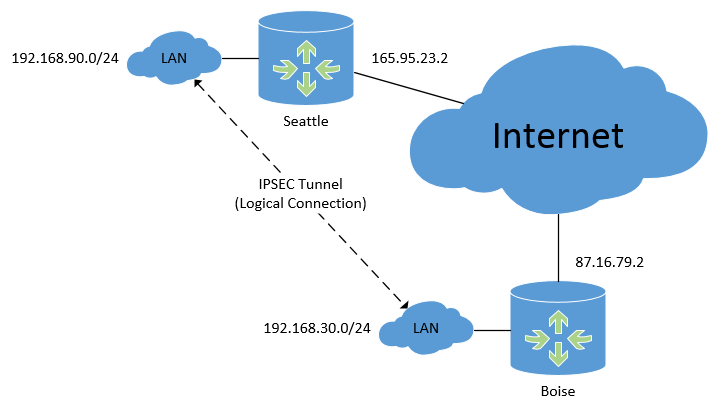
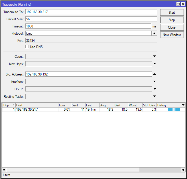
There's a very important distinction that needs to be made here - IPSEC isn't routing. IPSEC doesn't create virtual interfaces that are added to a route table like PPTP or GRE do. IPSEC isn't based on routing, it's based on policy. In fact in the diagram below when tracerouting from one LAN subnet to another through two branch routers and multiple Internet routers only one hop is seen.

IPSEC Topology

Below is the physical topology diagram of what we're working with, and it shows the logical connection that the IPSEC tunnel will create between subnets. Mikrotik IPSEC Topology
We have two routers, in Seattle and Boise, both connected to the Internet somehow with their own static IP addresses. These routers could be at two offices owned by one company, or just two locations that need to be connected together. We need computers or servers at one location to be able to contact devices at the other, and it has to be done securely. An IPSEC VPN is perfect for this sort of implementation.

Mikrotik IPSEC Peers

First, on each router we'll configure IPSEC peers. The peer will point to the opposite router's public IP address, with Seattle pointing to Boise and Boise pointing to Seattle. It's very important to add comments to your peer and policy entries, so you know which points to which.

Seattle Peer

On the Seattle router:
/ip ipsec peer add address=87.16.79.2/32 comment="Boise Peer" enc-algorithm=aes-128 nat-traversal=no secret=my_secret

Boise Peer

On the Boise router:
/ip ipsec peer add address=165.95.23.2/32 comment="Seattle Peer" enc-algorithm=aes-128 nat-traversal=no secret=my_great_secret
The encryption algorithm and secret must match, otherwise the IPSEC tunnel will never initiate properly. In production networks a much more robust secret key should be used. This is one time when network administrators often generate long random strings and use them for the secret, because it's not something a human will have to enter again by memory. Secret keys should be changed on a regular basis, perhaps every 6 or 12 months, or more often depending on your regulatory needs. Do not enable NAT traversal, it's pretty hit-or-miss. This feature is meant to help get around NAT'ing, which breaks IPSEC, but it doesn't always work necessarily.

Mikrotik IPSEC Policy

Second, we'll configure the IPSEC policies. These are what tells the router was traffic is "interesting" and should be sent over the tunnel instead of routed normally. Because this IPSEC tunnel will be a site-to-site tunnel connecting two networks (instead of hosts) we'll specify tunnel=yes in the configuration. This is also required per Infrastructure Router STIG Finding V-3008:
...ensure IPSec VPNs are established as tunnel type VPNs when transporting management traffic across an ip backbone network.
https://www.stigviewer.com/stig/network_devices/2015-09-22/finding/V-3008
If you look at the policies side-by-side you'll notice that the IP address entries on both routers are reversed - each router points to the other. It really helps to open up the same dialog boxes in two Winbox windows, looking at them side-by-side, checking that the SRC address on one router is the DST address on the other.

Seattle Policy

On the Seattle router:
/ip ipsec policy add comment="Boise Traffic" dst-address=192.168.30.0/24 sa-dst-address=87.16.79.2 sa-src-address=165.95.23.2 src-address=192.168.90.0/24 tunnel=yes

Boise Policy

On the Boise router:
/ip ipsec policy add comment="Seattle Traffic" dst-address=192.168.90.0/24 sa-dst-address=165.95.23.2 sa-src-address=87.16.79.2 src-address=192.168.30.0/24 tunnel=yes

Mikrotik NAT Bypass

If you're using NAT to send multiple internal LAN IPs out one interface to the Internet we'll need to bypass that. If we don't set up a NAT bypass the NAT process will snatch up our traffic before the IPSEC policies have a chance to move it over the tunnel, and those packets will get NAT'd out into oblivion. We'll create these NAT rules on each router, and move them up above any others.

Seattle NAT Bypass

On the Seattle router:
/ip firewall nat add chain=srcnat comment="Boise NAT bypass" dst-address=192.168.30.0/24 src-address=192.168.90.0/24

Boise NAT Bypass

On the Boise router:
/ip firewall nat add chain=srcnat comment="Seattle NAT bypass" dst-address=192.168.90.0/24 src-address=192.168.30.0/24

IPSEC Tunnel Testing

At this point we have everything needed for a functioning IPSEC tunnel. With that being said, most routers do not keep IPSEC tunnels up all the time. If no interesting traffic is being pushed over the tunnel most routers tear the tunnel down and don't bring it back up until the policies are triggered again with interesting traffic. This can create a tiny bit of latency when traffic first starts, a moment is needed to build the tunnel. RouterOS features like Netwatch and scheduled ping scripts can create traffic that keeps the tunnels up, but you shouldn't see an appreciable difference, especially if you're moving data frequently from one subnet to another.
For IPSEC tunnels that stay up all the time and also give you routed virtual interfaces, take a look at running GRE over IPSEC.
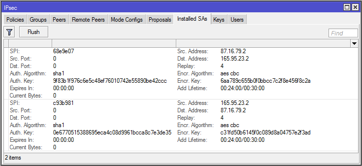
To force this IPSEC tunnel to come up I've sent pings from one subnet to the other, creating interesting traffic and triggering the IPSEC policy. When viewing the Installed SAs on the Boise router we can see that encryption keys have been established, and that on each side the SRC and DST addresses correspond with each other: Mikrotik Installed SA
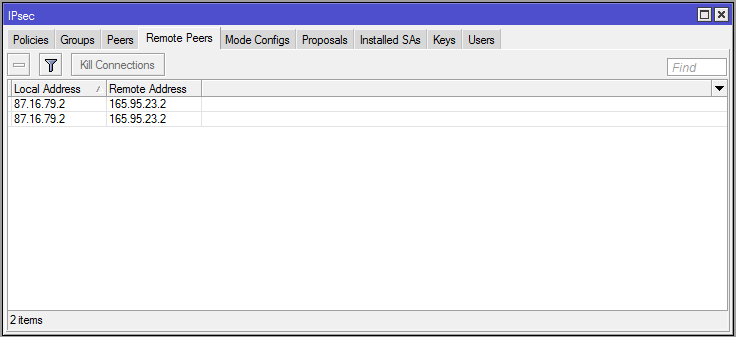
In the Remote Peers tab it also indicates that the Seattle router is an established remote peer: Mikrotik IPSEC Remote Peers
On the Seattle router you'll see the same information in the Installed SA and Remote Peers tab, but the IP addresses will be backwards from Boise's.
Tracerouting from an IP address on the Seattle LAN shows one hop to an IP address on the Boise LAN: Mikrotik IPSEC Traceroute
Notice that I specified the source address in the traceroute above. This is so that the packets sent for the traceroute will appear to originate inside the IPSEC policy's SRC network, and be headed to a DST network that matches the policy as well - interesting traffic. If you just try pinging straight from one router to another it won't work, because the packets won't match the policy and IPSEC will ignore them. Either specify the SRC to match the policy when pinging from the router, or ping from a real host inside those subnets.
There is a lot more we can do with IPSEC VPNs, like running GRE over a tunnel for routing or using OSPF, but this is a great start.
MikroTik IPSEC Site-to-Site Guide
11.00
The MikroTik IPSEC Site-to-Site Guide is over 30 pages of resources, notes, and commands for expanding your networks securely. The guide is a printable PDF so you can easily make notes and track your progress while building IPSEC tunnels. Included in the download are text files for each router's configuration with commands you can copy and paste directly to the terminal.
This guide uses a real-world network topology for creating secure site-to-site links in two scenarios. The first scenario is a basic link between LANs at separate locations using IPSEC. The second scenario uses IPSEC with GRE+OSPF to create secure, routed links that can scale to dozens of networks or more.


Fuente:
https://www.manitonetworks.com/mikrotik/2016/3/5/ipsec-tunnels